thermal bridges illustration

Thermal bridges: the temperature factor fRsi

We continue our series of articles on the topic of thermal bridges: this time, we illustrate the fRsi value, which describes the thermal ”strength” of a node under the point of view of internal surface temperatures.

As we have explained in a previous article, the PSI value describes a higher or lower heat flow caused by a discontinuity in the thermal envelope – a thermal bridge. On the other hand, the fRsi factor is of primary importance for health and comfort considerations.

To guarantee a comfortable environment, the thermal envelope needs to be as homogeneous as possible, so that the temperatures can be even over the internal surfaces. This principle is valid for new constructions as well as for energy retrofits, regardless of the overall energy efficiency level of the building. To achieve this, the thermal bridges of the building need to be designed and calculated not only under the point of view of the heat flow (PSI), but also to address the internal surface temperatures (fRsi).

A thermal bridge caused by the geometry of the structure, that generates a discontinuity in the thermal envelope.

THE TEMPERATURE FACTOR fRsi

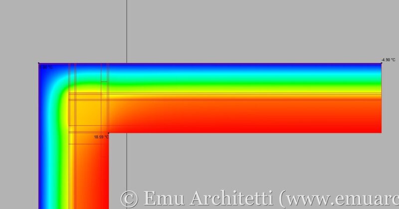
In winter, the “average” room temperature is guaranteed by the combination of the thermal envelope and the heating system. The same happens in the summertime if the building is provided with a cooling system. However, this does not mean that the internal temperatures are even over the internal surfaces. Because of discontinuities of the envelope (thermal bridges), the internal temperature is lower than the “average”. In summer, temperatures at thermal bridges are higher, depending on the dynamic behavior of the structure under the changing external conditions.

Raising the average temperature of the whole house by a few degrees does not help, because the surface temperature in the “weakest” spots remains lower. This phenomenon is caused by the fRsi temperature factor of the thermal bridge.

The fRsi factor is given by the difference between the internal temperature in the “weak” spot minus the external temperature, divided by the average temperature difference between inside and outside:

fRsi = ( Tmin – Te ) / ( Ti – Te )

Tmin: internal surface temperature at the thermal bridge;

Ti: internal room temperature;

Te: external temperature.

The difference between the internal room temperature and the external temperature is relatively easy to find. Design room temperature is usually 20 °C (68 °F), while the external temperature depends on the climate you are designing for. The minimum internal temperature at the thermal bridge (Tmin), however, requires a finite element calculation according to ISO 13788, based on the geometry of the node, and on the materials used in the construction. Please notice that the fRsi factor cannot be calculated from the internal temperature obtained from an ISO 10211 calculation, because the two norms assume different values as far as internal and external surface resistances.

The fRsi factor is a dimensionless number, ranging from 1 to 0.

fRsi = 1: the internal surface temperature at the thermal bridge is exactly the same as in the rest of the house. It is the best result you could ever get, and it is physically impossible to obtain;

fRsi = 0: the temperature at the thermal bridge is identical to the outside one, with a terrible outcome in terms of comfort. This result is also physically impossible.

If it is impossible to achieve a fRsi value of 1 where a thermal bridge is located, on the other hand, you should always try and get values as close to 1 as possible.

TEMPERATURE FACTOR AND COMFORT

A surface temperature that is lower than the “average” room temperature has several negative effects on the comfort and overall healthiness of the building.

From the point of view of thermal comfort, this temperature asymmetry makes us feel that a room is “cold”, even though the average temperature may be higher than normal room temperature. Under the same principle, the same room feels “warmer” in summer.

The combination of localized lower temperatures and high humidity (caused by lack of ventilation), fosters the appearance of mold and/or condensation exactly where the fRsi factor is at its lowest.

Mold inside a bathroom, caused by low surface temperatures and lack of ventilation. - photo by Damiano Chiarini.
Mold inside a bathroom, caused by low surface temperatures and lack of ventilation. – photo by Damiano Chiarini.

To avoid mold disasters, any work done on the thermal envelope should include a thorough analysis of the fRsi factors.

COMPARING fRsi FACTORS

When you design how to go about a specific thermal bridge, you can compare the “strength” of different solutions from a comfort point of view by comparing their fRsi values.

Calculation of the fRsi factor for the thermal bridge of a concrete column in a masonry wall, with an unmitigated solution (left) and a mitigated one (right).

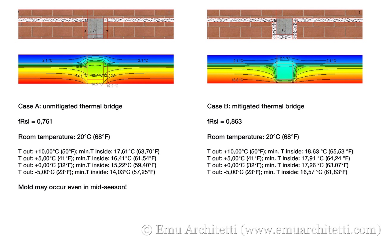
As shown in the graph, the unmitigated solution A (left) is going to foster mold growth even with mild outside temperatures, in spring and autumn.

CONCLUSIONS

To guarantee a comfortable and healthy indoor environment, the “weak” points of the thermal envelope (thermal bridges), need to be properly addressed.

Whether or not you are building/refurbishing to meet the Passive House standard, health needs to be a priority. The design of the thermal envelope should include the calculation of the fRsi factors of the thermal bridges, to obtain internal surface temperatures high enough to avoid the risk of mold and condensation.

The fRsi factor, as described in this article, can be used to compare different options to mitigate a thermal bridge, and to find out which one can guarantee the best comfort.

PSI values

Thermal bridges: the PSI value

For new builds as well as energy retrofits, the construction industry worldwide is shifting more and more towards zero energy buildings and Passive Houses.

With the thermal envelope becoming more and more advanced, the correct evaluation of thermal bridges becomes critical: in this article, we explain the PSI value.

We’re going to address the role of thermal bridges as far as comfort, including mold and condensation, in a separate article.

PARAMETERS

When you develop the energy design of a building, the first step to take is to determine the energy needed to keep the internal environment comfortable. It is called “net energy demand” because it does not take into account the building systems (including renewable energy sources). Only the following parameters are considered:

  • thermal coupling between the structures of the building (including windows) and the outside;
  • heat losses/gains via ventilation, including air leaks;
  • solar heat gains — the “passive” heating received through glazed components;
  • interior heat gains, provided by body heat and appliances.

The reference norm is ISO 13790, which is the base of PHPP, the calculation tool to design passive buildings. In the list above, thermal bridges are included in the first point.

In order to understand what a PSI value means, you need to understand how the thermal coupling between inside and outside is calculated.

The heat migrates spontaneously from a warmer body to a colder one, following the “easiest” path available. After all, heat is “lazy” enough to be predictable. In the real world, the heat flows through the structures of the thermal envelope following bidimensional or tridimensional paths.

The bidimensional heat flow through the structures of the thermal envelope - in this case, at a corner of the building.
The bi-dimensional heat flows through the structures of the thermal envelope — in this case, at a corner of the building.

When you design a building, however, the heat flow is calculated as if the heat would follow a straight line (mono-dimensional flow) from the warm side of the structure to the cold one. This is the bottom line of ISO 6946, which dictates how you calculate the thermal transmittance and R-value of an opaque structure.

The heat flow calculated in a mono-dimensional way is different from the one that occurs in reality (bidimensional or tridimensional heat flow). The difference between the two flows is the PSI value.

You need to be careful: the same thermal bridges can have different PSI values, depending on how the mono-dimensional flow is calculated.

We include here a double example, showing how the PSI value changes depending on whether the mono-dimensional flow is calculated according to the inside measurements of the structures, or to the outside ones (also see ISO 13789).

EXAMPLE: CALCULATING WITH INTERNAL MEASUREMENTS

Calculation according to internal measurements — see the green arrows in the image below — is used to determine the heat load of individual rooms.

The thermal bridge calculated according to the internal measurements, here represented by the green arrows in the picture.

The bidimensional heat flow — calculated with a finite element software according to ISO 10211 — is the following L2D value:

Bidimensional flow L2D: 0,5716 W/mK (0,3303 BTU/(h*ft*°F))

The mono dimensional heat flow, calculated according to the internal measurements, is calculated as follows:

Wall #1: 2,18 m * 0,103 W/m2K = 0,2245 W/mK (7,15 ft * 0,0181 BTU/(h*ft2*°F) = 0,1294 BTU/(h*ft*°F))

Wall #2: 2,57 m * 0,103 W/m2K = 0,2647 W/mK  (8,43 ft* 0,0181 BTU/(h*ft2*°F) = 0,1526 BTU/(h*ft*°F))

Total mono dimensional flow (L1D), internal measurements: 0,2245 + 0,2647 = 0,4892 W/mK. (0,2820 BTU/(h*ft*°F))

The difference between the bidimensional and mono dimensional heat flows , according to the internal measurements, is PSI-i:

PSI-i = L2D – L1D = 0,5716 – 0,4892 = 0,0824 W/mK. (0,3303 – 0,2820 = 0,0483 BTU/(h*ft*°F))

EXAMPLE: CALCULATING WITH EXERNAL MEASUREMENTS

Calculations according to the external measurements are used to evaluate the whole thermal envelope, as in the case of PHPP, because the results are more conservative.

Calculation with external measurements, represented by the green arrows.

The bidimensional flow is exactly the same as the example above — it would only change if we were to modify the geometry of the node, or the materials.

Bidimensional flow (L2D): 0,5716 W/mK (0,3303 BTU/(h*ft*°F));

The mono dimensional flow L1D changes, because this time we are calculating it according to the external measurements:

Wall #1: 2,74 m * 0,103 W/m2K = 0,2822 W/mK (8,99 ft * 0,0181 BTU/(h*ft2*°F) = 0,1627 BTU/(h*ft*°F))

Wall #2: 3,08 m * 0,103 W/m2K = 0,3172 W/mK (10,10 ft * 0,0181 BTU/(h*ft*°F) = 0,1828 BTU/(h*ft*°F))

Total mono dimensional flow (L1D), external measurements: 0,2822 + 0,3172 = 0,5994 W/mK (0,1627 + 0,1828 = 0,3455 BTU/h*ft*°F))

The difference between bidimensional and mono dimensional flows, according to the external measurements, is PSI-e:

PSI-e: L2D – L1D = 0,5716 – 0,5994 = -0,0278 W/mK (0,3303 – 0,3455 = -0,0152 BTU/(h*ft*°F))

NEGATIVE PSI VALUES

The numerical value of PSI is calculated via the arithmetic subtraction between the bidimensional flow L2D and the mono-dimensional one L1D: if the numerical value of L1D is higher than the one of L2D, as in the example above, the value of PSI is lower than zero. In terms of heat flow, a “negative” value of PSI has only a mathematical meaning: it does not express a value for the quality of the construction it refers to.

CONCLUSIONS

The double example above is useful to explain what the PSI value represents. It is just a number used to match the mono-dimensional flow to the bi-dimensional one. The numerical value of PSI changes based on how the overall heat calculation of the building is set up — either according to the internal measurements or to the external ones.

The same thermal bridge has different values of PSI, depending on how the building is calculated.

If you don’t know what the PSI value refers to, you cannot say whether it is “high” or “low.”

The PSI value cannot stand alone: it necessarily refers to specific structures and geometry.

If you want to compare the PSI values of different design solutions, you can only do it if these values are calculated in the same way.

compactness ratio of a building example

The compactness ratio or Form Factor of a building

When addressing the energy efficiency of a building, one of the most important players in the game is the compactness of its thermal envelope.

Is there a way to measure the compactness of a building? Yes: it’s the compactness ratio, sometimes referred to as the Form Factor.

This value is obtained by the sum of all surfaces of its envelope, divided by its gross heated volume.

Therefore, the Form Factor does not depend on whether or not a building is insulated, or on how much. Orientation does not play a role either: it only depends on the geometry of the thermal envelope.

Form Factor example

Let’s take one of the two passive houses of Cavriago as an example:

Sum of envelope surfaces: 554,56 m2 (5969,09 ft2);
Gross heated volume: 880,13 m3 (31057,63 ft3);
Form Factor: 0,63 1/m (0,19 1/ft).

3D model of one of the two passive houses of Cavriago.

When we were designing the two passive houses of Cavriago, we worked to keep the compactness ratio as low as possible, in order to maximize energy efficiency and minimize costs. Regardless of its insulation, orientation, or building systems, the lower the compactness ratio is, the more efficient the building is going to be, for both heating and cooling.

Energy efficiency starts with the very first preliminary architectural design: architects need to be aware of the consequences of their decisions in terms of energy efficiency.

The first energy designer is the project architect

If the architectural design does not keep the compactness ratio under control, making the building efficient may be very difficult and expensive. Because of poor architectural design, regardless of the insulation, some buildings cannot be upgraded to meet the passive house standard.

To draw a comparison to cars, we can say that compactness is to the thermal envelope, what an aerodynamic shape is to a fuel-efficient car.

Hummer
Fuel efficiency is not one of the core goals pursued in the design of this kind of car. Even if you were to implement the most efficient engine, this vehicle is never going to get as efficient as an aerodynamic, compact, and lightweight car. The same concept applies to the architectural design of a building. It is just as senseless to develop the geometry of the building without keeping an eye on the compactness of its thermal envelope, and to try and make it “efficient” at a later stage.
case-passive-di-cavriago-emu-architetti-008-existing-building
The more complex the geometry of the thermal envelope, the more expensive it is to make it efficient. The shape of some buildings is so complex, that it becomes physically impossible for them to reach the Passive House standard, regardless of the amount of insulation installed and the money spent.

To ease the work of architects during the preliminary design phase, the Passivhaus Institut released DesignPH, a plug-in for SketchUp that allows you to develop the architectural and energy design at the same time.

Time constant a building

The Building Time Constant: Your Key to Thermal Resilience

What is the Building’s Time Constant?

When the power goes out, how long does your home stay comfortable? The answer is directly related to a little-known but critical metric: the building time constant. This value measures how slowly a building reacts to changes in temperature, whether from a sudden cold snap or a power outage that disables your heating and cooling system. A building with a high time constant offers greater thermal resilience, maintaining safe indoor temperatures for a much longer period. This capability is known as passive survivability.

How is it Calculated?

The time constant isn’t a measure of a single material but of the building as a whole. It’s calculated by dividing the building’s internal heat capacity by the average heat loss through its thermal envelope.

In simpler terms, this depends on two things:

  1. Heat Storage: How much heat can be stored by the building’s interior mass (like concrete floors or thick plaster walls).
  2. Heat Loss: How well the building’s insulation and airtightness prevent that stored heat from escaping.

A well-insulated building that also has significant interior mass will have a high time constant. It holds onto heat for a long time, increasing its thermal resilience.

If you’re working on a Passive House project, the time constant is calculated automatically by PHPP (although it’s not an upfront result shown by default by the software).

Why Materials and Design Matter

The design of your building has a dramatic effect on its thermal resilience. Let’s compare two Passive House designs with identical, excellent insulation levels.

A house built with a lightweight timber frame has less mass in direct contact with the interior air. It might have a time constant of around 90 hours. In contrast, a house built with heavy masonry and exterior insulation might have a time constant closer to 200 hours.

Both are highly efficient, but the masonry house has far greater thermal resilience. Its massive walls store more thermal energy, allowing it to “coast” through a power outage or extreme weather event for days, maintaining a stable and comfortable temperature. This showcases how design choices directly influence passive survivability.

A high time constant is ideal for primary residences that are occupied continuously. For a building used intermittently, like a vacation home or school, a lower time constant can be better, allowing the heating system to bring it to a comfortable temperature more quickly. Understanding this concept allows us to design homes that are not only energy-efficient but also safe and resilient in a changing world.

Thermal Mass Alone Won’t Do

It’s important to note that thermal mass alone is not enough to achieve a high time constant. The foundation for strong thermal resilience starts with three critical steps:

  • outstanding air sealing
  • high-quality insulation without thermal bridging
  • high-performance windows

Only when these Passive House envelope requirements are in place does adding thermal capacity—such as increased interior mass—truly enhance a building’s ability to maintain comfortable temperatures during extreme events. In other words, boosting thermal mass improves thermal resilience and passive survivability, but only if the building envelope is already performing at a Passive House level.

Building Time Constant – FAQ

What is the time constant of a building?
The building time constant is a measurement of how long it takes for a building’s interior temperature to change in response to outdoor temperature shifts. A higher time constant means the building maintains a stable temperature for longer, indicating good thermal resilience.

What is passive survivability?
Passive survivability is a building’s ability to maintain safe and habitable conditions for its occupants during an extended power outage or interruption of heating or cooling. A high time constant is a key factor in achieving passive survivability.

How does thermal resilience relate to the time constant?
Thermal resilience is a building’s ability to withstand and adapt to extreme temperature events. The building time constant is a direct measure of this resilience—a longer time constant means the building is more resilient to outdoor temperature swings.

Meet the Mechanical Ventilation System

With this article, we’d like to cover a topic that is very important for both comfort and energy efficiency of buildings: the ventilation of the house.

Unfortunately, this matter is as important as it is unknown to most people. When it come to business professionals, at least in Italy, we see an overall lack of any knowledge on this topic, which is combined with the widespread resistance to change. This situation is currently fostering a building practice, for both renovations and new constructions, where the indoor air quality of houses and buildings in general is worse than some decades ago.

We’ll try and cover the topic one step at the time.

3D model of a passive house

COMFORT REQUIREMENTS

In order to live in comfortable conditions, an adult human being needs about 30 m3 (1060 ft3) of fresh air every hour. A child requires less, starting at 10 m3 (350 ft3) per hour, and increasing with age. Of course, this amount changes depending on the physical activity: in case of very active sports, the amount required can be a lot more.

A classic example is provided by the bedroom: in Italy, this room has an average net treatable area of about 15 m2 (160 ft2), and a height of 2,7 m (8,8 ft), so that the volume of air available inside the room is about 40 m3 (1400 ft3). If two adults sleep in the bedroom, the air available in the room allows them to breathe comfortably for less than one hour. They are going to spend the rest of the night with less oxygen than they would need, and with an excess of carbon dioxide and water vapour. Sleeping with the bedroom door open is not going to help much.

This is one of the main causes of mold and condensation appearing on the internal surface of walls and ceilings.

Overall, we are used to an extremely low quality of air inside our buildings.

Besides breathing, other daily activities in a house produce water vapour, including cooking, showering and personal hygiene, washing clothes and so on. In average, a family of four people produces about 10 litres (2,6 gal) of water vapour every single day.

To avoid the risk of mold and condensation, you need to eliminate this vapour somehow.

TRANSPIRABILITY OF THE HOUSE

Contrary to popular belief, transpirability of the structures (including walls, roof and so on) that build up the thermal envelope can expel only a minimum part of the water vapour produced inside the house. Even in the case of the “greenest” structure, with straw bale and timber walls and clay or lime plasters, the amount of vapour that actually goes through those structures is only about 5% of the total.

A straw bale house under construction.

For this reason, stating that an external insulation layer “chokes” your house, does not make sense: there’s really not much to choke to begin with.

The only way to guarantee indoor air quality in a building, and to eliminate the water vapour produced, is to provide ventilation.

According to Italian standard UNI10339, the ventilation required in a house is 0,5 1/h: for example, if the net volume of your apartment is 200 m3 (7060 ft3), you need to provide 100 m3 (3530 ft3) of fresh air every hour, to maintain it livable. If you live outside of Italy, you have different codes and therefore different numeric requirements, but the base concept is most likely the same.

CONTROLLED NATURAL VENTILATION

The very first way to manage this air exchange is by opening the windows. It corresponds to the image of the housewife that opens up the house every morning, to air it out.

housewife

However, in the 21st Century, this scenario raises the following doubts:

1- In today’s day and age, adults have jobs and kids go to school, so that the house remains closed up and empty throughout the day;

2 – The guarantee the required air exchange described above, you’d need to open all windows of your house for 10-15 minutes at regular intervals, 6 or 7 times per day, including at night;

3 – air moves naturally only due to temperature difference (including wind), therefore natural ventilation is effective only in winter. An ineffective manual ventilation fosters the risk of mold and condensation in mid season;

4 – exchanging 100 m3 (3530 ft3) of air every hour causes an extraordinary waste of energy for heating and cooling.

UNCONTROLLED NATURAL VENTILATION

This type of ventilation is represented by uncontrolled air leaks through cracks and gaps of the thermal envelope.

Although these leaks contribute to getting rid of the water vapour you produce inside the house, these air leaks only happen in winter, when the temperature difference between inside and outside is high enough.

For comfort and energy efficiency, air leaks are bad news.

Minnesota wall rot
Damages to a wooden house caused by leakages of warm and humid air from the inside of the house to the outside, through a non-airtight thermal envelope.

As far as the durability of the house, this type of ventilation can cause some serious damages. If warm and humid air leaks through the structures of the house towards the outside, it may bring to heavy water condensation within those structures. In winter, a one meter long (3,3 ft) thin crack can bring up to 800 g (28 ounces) of condensation water into the wall/roof every single day.

In case of a masonry or concrete structure, this water diminishes the insulative properties of the structure. In case of a wooden house, this phenomenon brings the structure to rot in a relatively short time (5-10 years).

For both renovations an new constructions, eliminating the uncontrolled natural ventilation (air leaks) needs to be one of the top priorities.

CONTROLLED MECHANICAL VENTILATION

3D model of a passive house, with the ventilation system highlighted.

Structures are not transpirant enough, manual ventilation is difficult and air leaks dangerous. For these reasons, the market offers a variety of systems to mechanically ventilate buildings. These systems allow to bring filtered fresh air to the living areas, and to extract humid air from kitchen, bathrooms, laundry rooms. The same systems come with an integrated heat recover, to warm up the incoming air using the heat contained in the exhaust air, without mixing the two flows.

In Italy, these systems are still mostly considered as an additional “gadget”, because most professionals – unaware of the indoor air quality requirements – only see them under the energy efficiency point of view. Only 1% of Italian houses is provided with mechanical ventilation.

You can divide these systems into two groups: centralised systems (one machine for the whole house, with ductwork to distribute the air), and decentralised systems (one small machine per room, no ductwork, less efficient heat recovery).

All of these systems are made by:

– a set of fans to move the air;

– a set of filters (that remove dust and pollen from the air);

– a heat recovery system;

– centralised systems include ductwork to distribute the air to different rooms.

At the time of this article, these systems are not yet compulsory in Italy. However, we include a mechanical ventilation system in all of our projects, whether it is a new construction or a renovation.

STEREOTYPES

Just like any other innovation, mechanical ventilation is facing some resistance from the most conservative part of the building industry. It is perceived as an “unnatural” solution. However, these professionals don’t provide real technical motivations, and are unable to provide with valid alternatives to fulfil the requirements described in this article, as well as to avoid mold and condensation problems.

CONCLUSIONS

In order to live in a healthy way, the human body requires certain environmental conditions. Our natural metabolism needs to receive a set amount of fresh air every hour, and to expel water vapour and carbon dioxide.

Since we spend most of our time inside a constructed environment, the buildings we live in need to match our metabolism.

In the last few decades, we changed the way we use buildings. Until the end of World War II, housewives were in charge of indoor air quality of the house, which they took care of by opening up the windows for a considerable amount of time. In the 21st Century, this model is outdated. Homes are inhabited mainly at night, while they remain closed and unoccupied during the daytime. This changed way we use buildings requires a different way we manage them, in order to guarantee comfort and hygiene.

Even though local legislation may be late on the subject of ventilation, the market already offers a variety of solutions to integrate the manual ventilation with a mechanical one.

Theses systems allow to guarantee the indoor air quality, keeping proper levels of oxiden, water vapour and carbon dioxide.

With the way we use houses today, the alternative to these systems is a moldy house.

DesignPH example

DesignPH: the SketchUp plug-in to design Passive Houses in 3D

We finally had the chance to test DesignPH, the SketchUp plug-in that allows you to carry out the preliminary design of passive buildings in 3D. Once the model is created, you can export the data to PHPP (the energy balance software for passive house design), to further the energy design in depth.

Even though this plug-in has been available on the market for a couple of years, since version 8.5 of PHPP, our recent meetings with passive house professionals  tell us that this tool is not yet very widespread. It is the case of Italy, as well as the impression we got from our recent trip to the USA.

For this article, we tried to model one of the two passive houses that we are currently building in Cavriago, Italy, to analyse the pros and cons of this software.

https://youtu.be/55SIgdA4lGc

I remember quite clearly the first time I opened the PHPP: it was version 6, and my immediate reaction was: “What in the world am I doing?” As an architect, I’ve always felt the need for visual support to my work. For sure, I feel much more comfortable sketching ideas rather than filling out endless Excel tables. And yet, up until now, passive house design has been dominated by tables and numbers.

The verification tab of PHPP v.7, the most recent one translated into Italian.

MODELING

In this Excel-dominated context, DesignPH seems a bit like a dream coming true: via an easy and intuitive tool such as SketchUp, this plug-in allows you to carry out the early design, developing at the same time the architectural concept as well as the energy one.

Anyone involved with high-efficiency buildings knows how much the early architectural design phase influences the energy efficiency of the future building, because it shapes its thermal envelope.

The volume of the thermal envelope of one of the two passive houses of Cavriago, Italy, during the DesignPH 3D modeling.
The volume of the thermal envelope of one of the two passive houses of Cavriago, Italy, during the 3D modeling.

Once you get started with the software, the first steps involve modelling the thermal envelope of the building, and optimising it as far as orientation, compactness, distribution of openings and so on.

In the second phase, you need to assign physical properties to the elements you created: walls, roof, openings can either be customised, or imported straight from the database of certified components of the Passivhaus Institut.

Once you create rectangles on the surface of the envelope, transforming them into openings is just one right-click away.
The components of the envelope, including construction systems and windows/doors: the data can either be entered by the user, or be easily imported from the PHI database.

It is not necessary to model the internal partitions of the building, whereas external elements need to be modelled if they cast shadows on glazed openings. Non-heated rooms can be modelled simply by entering a temperature reduction factor.

The volume created with the standard SketchUp modelling tools is transformed into a thermal block with DesignPH: the remaining step to take is to model the surrounding building and terrain.

As the final step, you need to model the surrounding buildings and other elements that can cast shadows onto the building. You can also import an approximate terrain model from Google Earth. After this step, the plug-in is able to assess the shading effect of external volumes onto the thermal envelope of the building, and to calculate the solar heat gains.

As far as climate data, the plug-in is provided with a wide range of data sets: for example, it includes 25 location for Italy. It doesn’t seem to be possible to customise climate data yet.

Climate data sets in DesignPH: list of locations available for Italy.

RESULTS

Once you complete the model, it is possible to run the preliminary energy calculation, to assess the heating energy demand of the building. The calculation run by the plug-is is based on the yearly average, and it does not require any interaction with PHPP in this phase. The results are less precise than a monthly calculation, however the main goal of DesignPH is to optimise architectural and thermal design at the same time.

The results of the preliminary calculation in DesignPH, obtained without any use of PHPP

You should not however be fooled by the user-friendliness of this plug-in: what you get is just a basic assessment. Important aspects of passive house design such as thermal bridges, air tightness, ventilation heat recovery and so on are assumed to be “average” by the software (this data is not entered by the user).

A result of 15 kWh/m2y from DesignPH does not mean that the building you designed is passive: it most likely means it needs to be improved, to allow for some leeway during the following PHPP calculation – which cannot be skipped if you want to build a passive building that actually works.

LANGUAGE, LICENSE, COST

At the date of this article, DesignPH is available in English and German. We don’t know whether or not the developers intend to add more languages in the future.

You can download a free demo version of the plug-in: keep in mind that it was developed for SketchUp v.8, although it is also available for the free versions of SketchUp 2013 and 2014.

Download the demo version of DesignPH for free

The license for DesignPH is sold separately from the one for PHPP: you can purchase them together or separately on the website of the Passivhaus Institut. On the same site, you can also find the most updated price for the current version for both softwares.

IMPORT/EXPORT

Once you have complete the model and run the preliminary calculation within DesignPH, you can export your data as a .ppp file: this can be imported directly into PHPP from version 8.5 on. To our knowledge, it is not possible to import this data in older versions of PHPP.

The same passive house of Cavriago, modeled in Archicad.

We did not try and import a 3D model into SketchUp from a different source, such as Archicad or Revit. Even though this is probably possible, our guess it that it is more advisable and faster to model the building from scratch.

We also did not try the opposite – exporting the 3D model from SketchUp+DesignPH: we’ll keep you posted once we do try.

CONCLUSIONS

DesignPH is no doubt an important new tool available to designers that work on passive building since the very preliminary phase. The plug-in is extremely intuitive, and perfectly integrated with SketchUp. Exporting data to PHPP is easy, and the overall workflow is much more fluid than PHPP alone.

With this tool, even designers that don’t have a strong energy background are able to optimise their architectural design, to achieve passive house standard.

On the other hand, it would be silly to assume that a simple SketchUp plug-in can be enough in the process of designing and building a passive house. After this preliminary design, further steps are needed, including PHPP calculation, as well as state of the art construction quality.

With DesignPH, and with more and more products suitable for passive house available on the market, this comfort and energy efficiency standard can be finally be made available to a broader base of architects and designer, to become more and more widespread around the world.

Energy Efficiency: the importance of site supervision

On our Facebook page, we are regularly publishing images from our Cavriago construction site, where we are building two Passive Houses.

With this article, we would like to show just two examples of the many construction errors that can occur during the scope of the works, even working with an accurate contractor, proving that careful site supervision is necessary to meet a high level of quality and efficiency.

The detail we are going to write about is the perimeter of the foundation of the thermal envelope. The foundation itself is a concrete slab sitting on top of a drainage layer made of cellular glass gravel. On the sides, the slab is insulated with a panel of cellular glass.

perimeter insulation - Emu Architetti
Detail photo: the concrete slab sits on top of the cellular glass gravel (on the left), with a panel of cellular glass as perimeter insulation.
The detail as designed. Arrow pointing to continuous insulation.
The detail as designed.
Heat flow through the detail as designed.
Isotherms along the detail as designed.

No matter what calculations or drawings are made during the design phase, such a delicate detail of the thermal envelope cannot be left to be executed without supervision.

In the case of our site in Cavriago, the work was executed very well, with a separation layer of polypropylene geotextile between the glass gravel and the concrete (see the white strip in the picture below).

before the perimeter insulation panel was installed
The detail as perfectly executed, before the perimeter insulation panel was installed.

PROBLEM #1: CONCRETE LEAKS

In some isolated spots, the concrete leaked out from underneath the formwork panel, as you can see in the image below.

Concrete leaked out from underneath the formwork
Concrete leaked out from underneath the formwork, and mixed with the glass gravel.

This is no doubt a thermal bridge. Is it a bad one? It depends. If you are building a Passive House, these details matter a lot.

We calculated the effect of this thermal bridge, using a finite element software:

Detail showing the concrete leak.
Heat flow: notice the concentration through the concrete leak.
Isotherms change because of the construction mistake.

According to our calculation, the concrete leak as shown would increase the heat flow through the detail by approximately 4,2%. Calculating the sum of the (few) leaks along the perimeter, it would bring an increase in net energy demand of the whole building of a full 1%. Is this a lot? For a passive building, it is.

When considering comfort, on the other hand, if this error is a few isolated spots (not continuous), it does not have a real effect on the indoor temperature.

PROBLEM #2: HOLES TO FIT REBARS

Another risk for unexpected thermal bridges is given by the holes made through the vertical insulation panels to allow rebars to connect the (warm) foundation concrete slab of the house to the adjacent one of the garage (not yet cast at the time the photos were taken).

The hole cut through the panel is about 30 mm high: if we sum up the individual lengths of these cuts along the perimeter of the foundation, the total amount reaches 7,20 m.

The rebars go through the vertical insulation panels.

Again, we calculated how bad it would have been if we had left this detail to the business as usual (BAU) practice to fill this void with standard concrete.

BAU detail, with the cut filled with concrete.
BAU heat flow.
BAU heat flow.
BAU isotherms.
BAU isotherms.

If not avoided, this BAU construction mistake would have increased the heat flow through the node by 4,6%, with an increase in the net energy demand of the whole building of 1,6%.

CONCLUSIONS

The higher the goal, the better the execution needs to be. This relies first on high quality design, and then on attentive site supervision.

In one single day of works, we risked making the whole building envelope 2,6% worse than designed. And we are just at the foundations of the building.

This is not necessarily the contractor’s fault: building is difficult. Among Client, Architects and Contractor there needs to be an understanding to maximize teamwork and communication. Whoever is in charge of site supervision needs to be present, and aware that these kinds of problems can happen and do matter.

On the bank on the right: the clumps of concrete mixed with glass gravel, once removed from the perimeter.
waterproof foam
The lower row of cuts have been filled with waterproof foam before casting the concrete. The top ones are going to be filled in the same way as well..
blackout-proof home graphic

The blackout-proof home: Passive House with high time constant

Last week, our region (Emilia, Italy) was pounded with what locals are calling “The Big Snow.” With it came very tangible proof of just how fragile our infrastructure is, particularly our electrical grid.

When my husband wrote this article, originally in Italian, FOUR DAYS after the February 6th Big Snow, more than 1000 homes in the province of Reggio Emilia alone were still without electricity, leaving 4,000 people to brave the cold, many without sufficient heating. How can we fix this problem?

The potential benefit of an early ‘Blower Door Test’.

In December, we ran a ‘Blower Door Test’ (according to EN13829) on our CasaClima Class A project, “Conte Re”, under construction near Albinea (in the province of Reggio Emilia, Italy). The windows and doors had not yet been installed, so plastic was covering the openings. The recently applied interior plaster was just starting to dry. The substructure and underlayment of the roof were in place, but we decided to hold off the completion of the roof until we could run this preliminary Blower Door Test.

Many of our colleagues wondered why we decided to run a test so early in the construction process. Usually this kind of assessment is made after the windows and doors are in place, and after the roof is complete. In that scenario, however, it would be already too late to address air infiltration in areas of the thermal envelope that are covered with insulation, such as external walls, roof, and delicate envelope intersection points (wall to roof; wall to window etc.).

We decided to run the test early, so that we could identify any air leaks and fix them before finishing the roof. Our team* (basically any subcontractor whose work penetrates the building envelope) was assembled and present for the test, ready to address any air leakages present in their work. We were sealed inside while our colleagues Cristian Guida and Gianni Giavarini (from Oikema) set up and executed the Blower Door Test and took the infiltration measurements.

The main challenge of doing this, we quickly discovered, is that in order to get the correct amount of pressurization inside the house, the temporary coverings over the windows need to be fixed fairly well (which they were not). We had a few pop out the first time we ran the fan, but they were quickly reinforced and checked for any holes. Instead of pressurizing the whole house at once, we separated it into zones (this was made easier by the way this particular house was designed). In this way, we could go upstairs, seal half of that floor, run the Blower Door Test, and go around and check where each rafter met the collar beam.

In the roof, we found some infiltration at the corners (the weakest spot for airtightness), and around some pipe crossings. There was also some evidence of air movement at the ridge beam. However, we later attributed this to air passing between two rooms. Most of the rafters read a negligible level of air movement. Once we identified which ones needed to be sealed more, our roofer was on the job immediately, taping up any small holes. The hydraulic and electric openings were checked for air leakages as well, with minimal fixes needing to be made.

While an early test like this one is not required for CasaClima certification (or Passive House), we felt that it contributed greatly to our understanding of vulnerable points in the building envelope for air infiltration. Now, before proceeding with the completion of the roof, a second pass will be made over these points. Down the line, at the completion of the construction site, another Blower Door Test will provide the numbers that will qualify the construction for its CasaClima Class A certification. To learn more about CasaClima, please read our articles on this blog and subscribe to our newsletter.

*A big thanks to the members of our project team who helped out Friday: contractor (Nicola Lucci of Montanari Luigi), bricklayers (Tabba, Ali, and Assran), electrician (Massimo Malvisi), plumber (Davide Morini), window and door installer (Maurizio), roofer (Pierluigi Confetti of Confetti Legnami), and Blower Door Testers (Cristian Guida and Gianni Giavarini from Oikema)

The “Conte Re” house is for sale by Roverella SRL.

Passive house: new construction or renovation?

Passive House - Passivhaus - ItalyIn our blog, we are dedicating a large number of articles to deep energy retrofits, on one hand, and Passive Houses on the other. However, these two topics are not necessarily distinct from one another: here, we explain why.

When discussing “renovations” or “retrofits”, clearly we’re looking at the modification of an existing structure. The semantics (renovation, retrofit, refurbishment, etc) simply distinguish the level of involvement and general scope of works.

The term “Passive House”, instead, represents a project goal as far as health and comfort, and energy efficiency, whether it is a new construction or a renovation. For a comprehensive definition of what a Passive House is, you can read our article about it.

Is it possible to achieve passive standard in case of a building renovation or retrofit?

Yes, absolutely.

Is it always convenient (or cost efficient) to do so?

Not always. Here’s why:

In order to work, a passive building needs to be able to receive passive heating from the sun, as well as to make good use of the heat produced by the people living in it and by the appliances (lighting, home appliances, computers etc.). For the building to rely only on these heat sources, its thermal envelope needs to be compact, well insulated, without thermal bridges or air leakages; and its openings need to be mostly oriented towards the equator.

When a new construction is designed from scratch, it is possible to integrate all these concept from the preliminary stages. This way, the energy efficiency of the building can be maximized, while keeping construction costs low. Compact form and orientation towards the sun determine what the heating/cooling demand of the building is going to be: these factors are a lot more important than any HVAC system or insulation material. For this reason, the design of a Passive House, and more generally of a sustainable building, requires an integrated design approach, where different aspects of the design are developed together, including the thermal envelope, the load bearing and seismic-proof structures, building services, acoustics and so on.

When you are working on an existing building, many of these factors are already given. It is often impossible to modify the shape or the orientation of a building. Consequently, the thermal envelope is going to receive less free heating from the sun, and the heat losses are likely to be higher. This does not mean that it is impossible to achieve the passive goal in case of a building renovation/retrofit: it means that it is not always convenient to pursuit this goal at all costs.

Buildings – like people – are all different from one another. It is impossible to find a one-size-fits-all solution to be applied in any circumstance. Location, orientation, compactness, construction material need to be taken into account. Furthermore: in case of a complete building renovation, where the works also involve the load bearing structures and the inner partitions, the overall evaluation has to be extended to factors that go beyond comfort and energy savings. What are the conditions of the bearing structure? Is the building even worth keeping? Is it necessary/possible to improve the seismic resistance of the structure? What about universal access? Are there barriers? Is it possible to remove them? Is it necessary/possible to improve the acoustic performance of the building?

For the decades to come, building retrofit represents probably the most important development for the construction industry in Italy. The topic is vast and complex. The potential is also very high: improvement of quality of life, economic development and energy savings. These kinds of projects, however, require higher technical skills from designers, in order to avoid gross design mistakes, that often turn out in disasters. Current Italian technical norms fall behind, and cannot guarantee proper building quality as far as health and comfort.

The passive standard is likely to become the future of the European construction industry – for new construction – starting from 2020, even though the 2010/31/EU Directive about Near Zero Energy Buildings still contains some grey areas. In one of our articles, we explained the great difference between the two concepts.

As far as renovations/retrofits are concerned, the passive standard needs to represent a goal, even though project-specific conditions are going to determine to what degree it can be applied. In these cases, in fact, it is more important to have a clear overall picture and aim to improve the building as a whole, including the bearing structure, the thermal bridges and so on. Energy efficiency can then be a secondary area of focus.